Micrel, Inc.
MIC2593
September 2008
23
M9999-092208
50ms, I
LOAD(CONT, MAX)
is 5.0A, the slow-trip threshold is
50Mv nominal, and the fast-trip threshold is 100mV. If the
output is connected to a 0.60& load, the output current
from the MOSFET for the slot in question will be regulated
to 5.0A for 50ms before the MIC2593 circuit breaker trips.
During that time, the dissipation in the MOSFET is given
by:
[
]
2V
5A(0.6&A
5V
E
I
E
P
MOSFET
=
=
?/DIV>
=
(
)
50ms
for
10W
5A
2V
P
MOSFET
=
?/DIV>
=
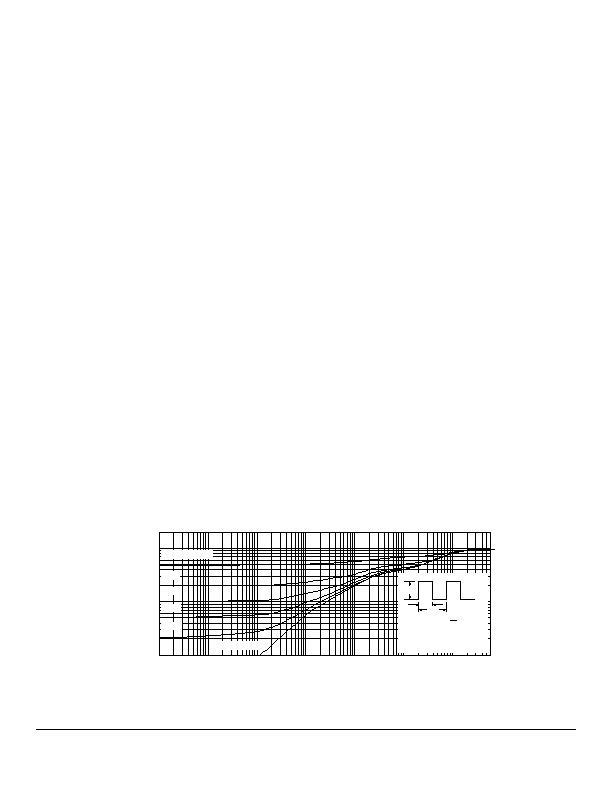
At first glance, it would appear that a really hefty MOSFET
is required to withstand this sort of fault condition. This is
where the transient thermal impedance curves become
very useful. Figure 13 shows the curve for the Vishay
(Siliconix) Si4430DY, a commonly used SO-8 power
MOSFET.
Taking the simplest case first, well assume that once a
fault event such as the one in question occurs, it will be a
long time, several seconds, before the fault is isolated and
the channel is reset. In such a case, we can approximate
this as a
single pulse
event, that is to say, theres no
significant duty cycle. Then, reading up from the X-axis at
the point where
Square Wave Pulse Duration
is equal to
0.1sec (=100msec), we see that the Z
?JA)
of this MOSFET
to a highly infrequent event of this duration is only 7% of
its continuous R
?JA)
.
This particular part is specified as having an R
?JA)
of
35癈/W for intervals of 10 seconds or less. Thus:
Assume T
A
= 55癈 maximum, 1 square inch of copper at
the drain leads, no airflow.
Recalling from our previous approximation hint, the part
has an R
ON
of (0.014/2) = 7m& at 25癈.
Assume it has been carrying just about 5A for some time.
When performing this calculation, be sure to use the
highest anticipated ambient temperature (T
A(MAX)
) in which
the MOSFET will be operating as the starting
temperature, and find the operating junction temperature
increase (T
J
) from that point. Then, as shown next, the
final junction temperature is found by adding T
A(MAX)
and
T
J
. Since this is not a closed-form equation, getting a
close approximation may take one or two iterations, but
its not a hard calculation to perform and tends to
converge quickly.
Then the starting (steady-state) T
J
is:
J
A(MAX)
J
擳
T
T
)
C)(R
)(0.005
T
(T
R
T
ON
A
A(MAX)
ON
A(MAX)
?/DIV>
?JA)
2
R
I ?/DIV>
?/DIV>
]
7m&m
C)(0.005)(
25
C
(55
7m&
C
55
T
J
?/DIV>
?/DIV>
?/DIV>
C/W)
(35
(5A)
2
?/DIV>
?/DIV>
?/DIV>
C)
(35
(0.20125W)
C
55
T
J
?/DIV>
?/DIV>
C
62.0?nbsp
Iterate the calculation once to see if this value is within a
few percent of the expected final value. For this iteration
we will start with T
J
equal to the already calculated value
of 62.0癈:
]
7m&m
C)(0.005)(
25
C
(62.0
7m&
T
T
A
J
?/DIV>
?/DIV>
C/W)
(35
(5A)
2
?/DIV>
?/DIV>
?/DIV>
C
62.35
C)
(35
(0.20125W)
C
55
T
J
?/DIV>
E
?/DIV>
?/DIV>
So our original approximation of 62.0癈 was very close to
the correct value. We will use T
J
= 62癈.
Finally, add (10W)(35癈/W)(0.07) = 24.5癈 to the steady-
state T
J
to get T
J(TRANSIENT MAX.)
= 86.5癈. This is an
acceptable maximum junction temperature for this part.
10
-4
10
-3
10
-2
10
-1
1
10
100
600
2
1
0.1
0.01
0.2
0.1
0.05
0.02
Single Pulse
Duty Cycle = 0.5
Normalized Thermal Transient Imperance, Juction-to-Ambient
1. Duty Cycle, D =
2. Per Unit Base = R
qJA
= 67癈/W
3. T
JM
T
A
= P
DM
Z
qJA
(t)
4. Surface Mounted
t
1
t
2
t
1
t
2
Notes:
P
DM
Square Wave Pulse Duration (sec)
Figure 13. Si4430DY MOSFET Transient Thermal Impedance Curve
发布紧急采购,3分钟左右您将得到回复。
相关PDF资料
MIC2594-2BM TR
IC CTRLR HOT SWAP NEG HV 8-SOIC
MIC2595R-2BM TR
IC CTRLR HOT SWAP NEG HV 14-SOIC
MIC280-7BM6 TR
IC SUPERVISOR THERMAL SOT23-6
MIC2800-GFSYML TR
IC REG TRPL BUCK/LINEAR 16MLF
MIC281-7BM6 TR
IC SUPERVISOR THERMAL SOT23-6
MIC2810-1JGMYML TR
IC REG TRPL BUCK/LINEAR 16MLF
MIC284-2BMM TR
IC SUPERVISOR THERM 2ZONE 8-MSOP
MIC3385-1.5YHL TR
IC REG DL BCK/LINEAR SYNC 14-MLF
相关代理商/技术参数
MIC2593-2YTQ
功能描述:热插拔功率分布 Dual-slot PCI Hot Swap Power Controller w/o IPMI support - Lead Free
RoHS:否 制造商:Texas Instruments 产品:Controllers & Switches 电流限制: 电源电压-最大:7 V 电源电压-最小:- 0.3 V 工作温度范围: 功率耗散: 安装风格:SMD/SMT 封装 / 箱体:MSOP-8 封装:Tube
MIC2593-2YTQ TR
功能描述:热插拔功率分布 Dual-slot PCI Hot Swap Power Controller w/o IPMI support - Lead Free
RoHS:否 制造商:Texas Instruments 产品:Controllers & Switches 电流限制: 电源电压-最大:7 V 电源电压-最小:- 0.3 V 工作温度范围: 功率耗散: 安装风格:SMD/SMT 封装 / 箱体:MSOP-8 封装:Tube
MIC2594-1BM
功能描述:IC CTRLR HOT SWAP NEG HV 8-SOIC RoHS:否 类别:集成电路 (IC) >> PMIC - 热交换 系列:- 产品培训模块:Obsolescence Mitigation Program 标准包装:100 系列:- 类型:热插拔开关 应用:通用 内部开关:是 电流限制:可调 电源电压:9 V ~ 13.2 V 工作温度:-40°C ~ 150°C 安装类型:表面贴装 封装/外壳:10-WFDFN 裸露焊盘 供应商设备封装:10-TDFN-EP(3x3) 包装:管件
MIC2594-1BM TR
功能描述:IC CTRLR HOT SWAP NEG HV 8-SOIC RoHS:否 类别:集成电路 (IC) >> PMIC - 热交换 系列:- 产品培训模块:Obsolescence Mitigation Program 标准包装:100 系列:- 类型:热插拔开关 应用:通用 内部开关:是 电流限制:可调 电源电压:9 V ~ 13.2 V 工作温度:-40°C ~ 150°C 安装类型:表面贴装 封装/外壳:10-WFDFN 裸露焊盘 供应商设备封装:10-TDFN-EP(3x3) 包装:管件
MIC2594-1YM
功能描述:热插拔功率分布 Negative Voltage Hot-Swap Controller - Lead Free
RoHS:否 制造商:Texas Instruments 产品:Controllers & Switches 电流限制: 电源电压-最大:7 V 电源电压-最小:- 0.3 V 工作温度范围: 功率耗散: 安装风格:SMD/SMT 封装 / 箱体:MSOP-8 封装:Tube
MIC2594-1YM TR
功能描述:热插拔功率分布 Negative Voltage Hot-Swap Controller - Lead Free
RoHS:否 制造商:Texas Instruments 产品:Controllers & Switches 电流限制: 电源电压-最大:7 V 电源电压-最小:- 0.3 V 工作温度范围: 功率耗散: 安装风格:SMD/SMT 封装 / 箱体:MSOP-8 封装:Tube
MIC2594-1YM-TR
功能描述:Hot Swap Controller 1 Channel -48V 8-SOIC 制造商:microchip technology 系列:- 包装:剪切带(CT) 零件状态:停产 类型:热交换控制器 通道数:1 内部开关:无 应用:-48V 特性:故障超时,闭锁故障 可编程特性:限流,压摆率,UVLO 电压 - 电源:-80 V ~ -19 V 电流 - 输出(最大值):- 工作温度:-40°C ~ 85°C 电流 - 电源:3mA 安装类型:表面贴装 封装/外壳:8-SOIC(0.154",3.90mm 宽) 供应商器件封装:8-SOIC 功能引脚:DRAIN,OFF,ON,PWRGD 标准包装:1
MIC2594-2BM
功能描述:IC CTRLR HOT SWAP NEG HV 8-SOIC RoHS:否 类别:集成电路 (IC) >> PMIC - 热交换 系列:- 产品培训模块:Obsolescence Mitigation Program 标准包装:100 系列:- 类型:热插拔开关 应用:通用 内部开关:是 电流限制:可调 电源电压:9 V ~ 13.2 V 工作温度:-40°C ~ 150°C 安装类型:表面贴装 封装/外壳:10-WFDFN 裸露焊盘 供应商设备封装:10-TDFN-EP(3x3) 包装:管件